Modbus Rules
Modbus Rules refers to a Modbus Command that NexusIM gateway act as a Modbus Master to acquire data from Modbus slave devices. One rule including assigned which interface for slave device, the slave device ID, the Modbus function code, (Read Holding Register) Start address, quantity count, data type…and other parameters.
Go to Sensor Data >> Devices and Rules >> Modbus Rules to view and configure Modbus commands list for slave devices.
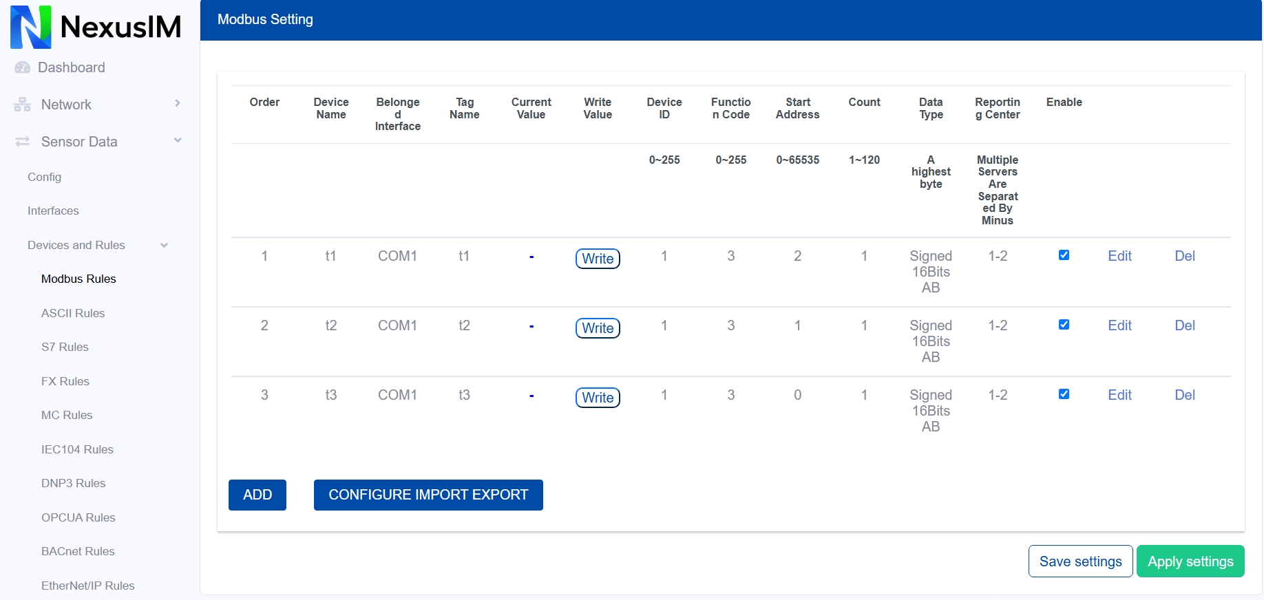
- The order of Modbus rules.
- Specify the Device Name when adding a Modbus rule.
- Configure the interface to which the rule applies.
- Configure the Tag Name for the specified register value. Multiple tags can be separated with semicolons when reading continuous registers.
- Preview the current value collected from the southbound device under this rule communication.
- Configure the slave device ID.
- Configure the Modbus command function code, for example,
3for Read Holding Registers. - Configure the read starting address.
- Configure the read quantity.
- Configure the register data type.
- Specify the reporting center to which the collected data is reported. The number corresponds to Servers > Reporting Center > Server (
1-5). - Enable or disable the rule.
- Edit the added rule.
- Delete the added rule.
- Add a new rule.
- Export or import the rules configuration as a CSV template file. This is useful for configuration backups and batch operations.
Add a Modbus Rule
This example reads a temperature and humidity sensor that uses the Modbus RTU protocol over an RS485 interface.
The following sensor datasheet example reads the temperature and humidity values from device address 0x01.
Inquiry frame (hexadecimal)
| Address code | Function code | Starting address | Data length | Check code low | Check code high |
|---|---|---|---|---|---|
0x01 | 0x03 | 0x00 0x00 | 0x00 0x02 | 0xC4 | 0x0B |
Response frame (hexadecimal)
For this example, the temperature is 30.5 C and the humidity is 48.6%RH.
| Address code | Function code | Returned byte count | Humidity value | Temperature value | Check code low | Check code high |
|---|---|---|---|---|---|---|
0x01 | 0x03 | 0x04 | 0x01 0xE6 | 0x01 0x31 | 0xDA | 0x7C |
Temperature calculation: 0x0131 = 305; actual temperature = 305 / 10 = 30.5 C.
Humidity calculation: 0x01E6 = 486; actual humidity = 486 / 10 = 48.6%RH.
The temperature and humidity read command is 01 03 00 00 00 02 C4 0B.
The response data is 01 03 04 01 E6 01 31 DA 7C.
Because the raw values are divided by 10, configure the Modbus Rule on the NexusIM gateway as follows:
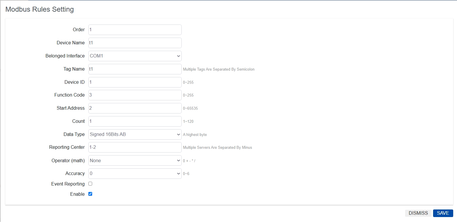
- Set the rule order.
- Specify the Device Name.
- Configure the interface. In this example, the temperature and humidity sensor is connected to the
COM1-RS485port. - Configure the Tag Name for the register values. Multiple tags can be separated with semicolons when reading continuous registers.
- Configure the sensor Device ID.
- Configure the Modbus command function code. In this example, the function code is
3for Read Holding Registers. - Configure the read starting address.
- Configure the read quantity.
- Configure the register data type according to the sensor datasheet.
- Specify the reporting center to which the collected data is reported. The number corresponds to Servers > Reporting Center > Server (
1-5). - Configure the operator function:
None,+,-,*,/, orExpression. - Configure the operand.
- Configure the accuracy of the calculated value.
- Enable or disable SMS and email reporting. A report is sent to the specified phone number and email address when the value changes or falls outside the configured range.
- Enable or disable the rule.
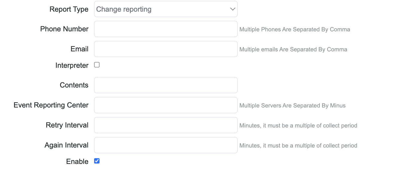
The following example shows the event reporting configuration: